
Basic Electrical Concepts
Every electrical specification you read, every motor nameplate you study, and every conversation you have with an electrician or site engineer uses the same four fundamental quantities. Understanding what they mean is the foundation of everything that follows.
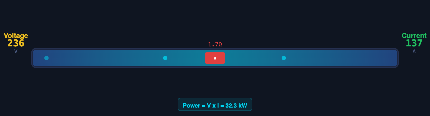
Voltage (V) — The Pressure
Voltage is the electrical potential difference between two points — the driving force that pushes current through a circuit. Think of it as the water pressure in a pipe. Common voltages in construction equipment: 230 V single-phase (site offices, small tools), 400 V three-phase (motors, batching plant, heavy machinery), 24 V DC (control circuits, sensors, PLC signals).
Current (A) — The Flow Rate
Current is the rate at which electric charge flows through a conductor — the actual movement of electrons. Like water flow rate in a pipe. More current through a motor means more mechanical output — or more heat. Current is what trips circuit breakers and burns out cables. Every cable, contactor, and breaker in a panel is rated for a maximum current. Exceeding that rating means heat, then fire.
Resistance (Ω) — The Friction
Resistance opposes current flow. All conductors have some resistance — cables, connections, motor windings. Loose connections and corroded terminals have much higher resistance than clean, tight ones. Higher resistance means more voltage is dropped across that connection and more heat is generated. A warm connection is a failing connection.
Power (W, kW) — The Work Rate
Electrical power is the rate at which electrical energy is consumed or produced. A 15 kW motor draws 15 kJ of electrical energy every second from the supply and converts it to mechanical power (minus losses as heat). Power is what you pay for on your electricity bill and what determines cable and panel sizing.
P (kW) = √3 × V × I × power factor (three-phase)
Power factor (PF) is the ratio of real power (doing useful work) to apparent power (drawn from the supply). Induction motors have a power factor of 0.7–0.9. A PF of 0.8 means 80% of the current drawn from the supply is doing useful work; 20% is magnetising the motor windings and cycling back to the supply without doing work. Low power factor increases cable and breaker sizing requirements and can attract utility penalties on large industrial sites. This is why large batching plants sometimes include power factor correction capacitor banks.
AC vs DC — Where Each Is Used
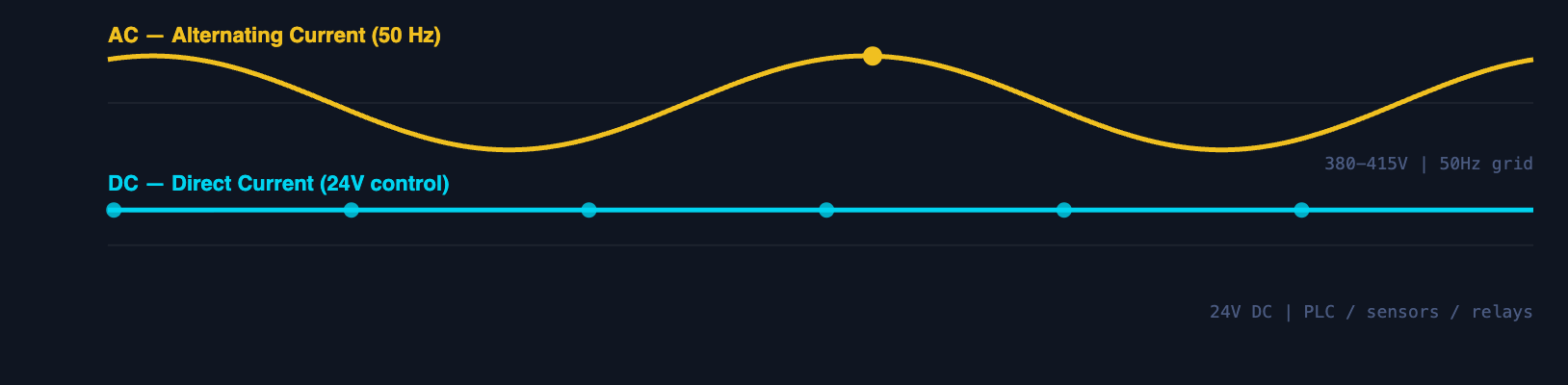
Voltage reverses direction 50 times per second (50 Hz in most of the world). Generated by power stations and delivered through the grid. Efficient to transmit over long distances via transformers. The standard for all mains-powered industrial equipment.
→ All motor power circuits
→ Heaters, lighting, welding
→ Transformers work on AC only
Voltage is constant, always flowing in one direction. Produced by batteries or by rectifying AC. Used in control circuits because it is stable, easy to logic-switch, and safe at low voltages. PLCs, sensors, relays, and communication all run on 24 V DC.
→ Sensor circuits (4–20 mA)
→ Control panel logic
→ Variable speed drive electronics
Almost every modern machine has two electrical systems running simultaneously: a 400 V AC power circuit driving the motors, and a 24 V DC control circuit operating the PLC, sensors, and relays. The two circuits are isolated by a transformer and separate fusing. When a technician says "the control circuit is dead," they mean the 24 V DC supply has failed — the motors may be fine. When they say "phase failure," the 400 V AC supply has a problem. These are completely separate issues with different diagnostic paths.
Single-Phase vs Three-Phase Power
Industrial construction equipment almost always runs on three-phase power. Understanding why — and what to check when a site cannot supply it — is essential for equipment commissioning conversations.
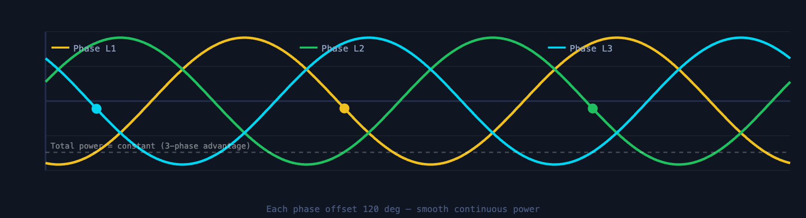
Single-phase power (230 V in most countries) uses two conductors — live and neutral. Voltage alternates sinusoidally, meaning instantaneous power delivery pulses between zero and maximum 100 times per second. This pulsing makes single-phase motors less efficient and limited in size.
Three-phase power uses three live conductors, each carrying a sinusoidal voltage but offset 120° apart in time. The three phases together deliver nearly constant instantaneous power — the contributions from each phase always sum to a smooth total. This is why three-phase motors are smoother, more efficient, and can be built to any size.
Three-phase delivers 3× the power of single-phase at the same voltage and current. A 400 V three-phase supply can power a 75 kW motor. The same voltage single-phase cannot.
Three-phase transmits the same power with less conductor material than single-phase. The neutral conductor can be smaller or absent in balanced three-phase loads.
Three-phase induction motors start themselves with no extra components. Single-phase motors require capacitors and start windings — more complexity, lower reliability.
A batching plant with a total connected load of 120 kW requires a three-phase 400 V supply sized for at least 200 A (accounting for motor starting surges and demand factor). A generator sized for 120 kW running load will trip when the largest motor starts, because startup current is 5–7× nameplate current. The sales conversation should happen before delivery: confirm available supply, transformer capacity, and cable run distance from the panel to the plant. Voltage drop over a long cable run can reduce motor terminal voltage enough to affect starting torque.
How Electrical Power Flows in a Machine
Every machine powered from the mains follows the same hierarchy: Source → Protection → Control → Load. Understanding this chain lets you trace faults logically and explain panel layouts to clients.
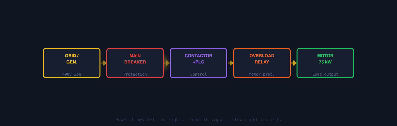
400 V three-phase supply enters the main panel via the incoming cable and main isolator switch.
Circuit breakers and overload relays protect cables and motors from excess current. Trip before damage occurs.
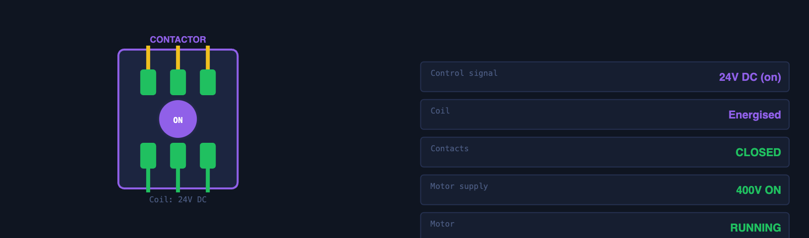
Contactors switch motors on/off under PLC command. The control circuit (24 V DC) commands the power circuit (400 V AC).
The motor converts electrical power to mechanical work: rotating the mixer, driving the conveyor, pumping water.
Main Electrical Components
Automatically disconnects a circuit when current exceeds its rated value or when a short circuit occurs. Protects cables from overheating. Rated in amps (e.g. 63 A). Can be reset after the fault is cleared — unlike fuses, which must be replaced. Main breaker in every panel; individual breakers per motor or circuit.
→ Individual motor circuit breakers
→ Control circuit MCB (miniature circuit breaker)
An electrically operated switch that handles high power. A small 24 V DC coil signal closes the contactor's main contacts, allowing 400 V AC to flow to the motor. When the PLC removes the coil signal, the contacts open and the motor stops. Unlike a manual switch, contactors handle thousands of switching operations and are designed for motor loads.
→ Star-delta starter (uses 2–3 contactors)
→ Reversing starter (two contactors, interlocked)
A smaller version of a contactor for lower-power switching. A control signal (typically 24 V DC) energises a coil that switches one or more sets of contacts. Used extensively in control circuits to route logic signals, create interlocks (motor B cannot start until motor A is running), and interface between PLC outputs and external devices.
→ Signal relay from PLC to solenoid valve
→ Fault relay for alarm indication
Protects the motor from sustained overcurrent — typically caused by mechanical overload (blocked conveyor, jammed mixer). Measures motor current continuously using a bimetallic strip or electronic current sensing. Trips if current exceeds the set value for more than a few seconds. Must be set to match the motor's nameplate current rating.
→ Electronic overload relay on modern panels
→ Set point: 100–110% of motor FLA
Changes voltage from one level to another using electromagnetic induction. Works only on AC. Steps down 400 V AC to 24 V AC (then rectified to 24 V DC) for the control panel. Also used to create isolated circuits — the control circuit transformer means faults in the 24 V control circuit cannot damage the 400 V power circuit.
→ Step-down transformer for lighting circuits
→ Isolation transformer for sensitive instrumentation
Converts fixed-frequency AC supply (50 Hz) to a variable frequency and voltage output, allowing precise motor speed control. By varying the frequency supplied to the motor, speed can be controlled from near-zero to above nameplate speed. Also provides soft-start, eliminating the startup current surge of direct-on-line starting.
→ Conveyor speed adjustment
→ Fan speed control for energy saving
→ Soft-start for large motors
Motors — The Primary Electrical Load
In most construction and industrial equipment, the motor is the reason for the entire electrical system. Everything else — the panel, the cables, the breakers, the contactors — exists to deliver power to the motor safely and controllably.
The Induction Motor
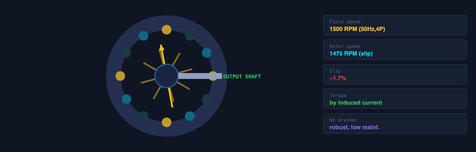
The three-phase induction motor is the workhorse of industrial machinery. It has no brushes, no commutator, and no physical electrical connection to the rotor — the rotor is driven entirely by electromagnetic induction. This makes it extraordinarily reliable, low-maintenance, and robust in dusty, wet, or vibrating environments.
How it works, simply: the three-phase supply creates a rotating magnetic field in the stator (the stationary part). This rotating field induces currents in the rotor conductors. Those induced currents create their own magnetic field, which reacts against the stator field, producing torque and rotation. The rotor always spins slightly slower than the field (this slip is necessary for induction to occur).
Reading a Motor Nameplate
Every motor has a nameplate — a metal plate attached to its frame listing its key specifications. Being able to read and interpret these is a core sales skill when specifying or replacing motors.
Full Load Amps (FLA) is the current the motor draws at its rated power output. It is the number used to: set the overload relay (typically 100–110% of FLA), size the supply cable, size the contactor, and size the circuit breaker (typically 125–160% of FLA). If a motor's overload relay is set above FLA, the motor is unprotected. If a client reports "the overload keeps tripping," the first questions are: what is the FLA, what is the overload set to, and what is the motor actually drawing? These three numbers will identify whether it is a motor fault, a mechanical overload, or a wrong setting.
A site engineer reports:
"The conveyor motor trips on overload every time we run it under full load. The motor is
rated 7.5 kW."
Diagnostic path: Check the overload relay setting — is it set to the motor's FLA? Check actual
running current with a clamp meter. If actual current exceeds FLA, the motor is mechanically
overloaded: belt too tight, bearing seized, load too heavy. If actual current is at or below
FLA but the overload is tripping, the relay is set too low or is faulty. If the motor draws
high current at startup and the relay trips during starting, a different relay class (Class 20
vs Class 10) or a soft-starter is needed.
Sensors and Basic Control
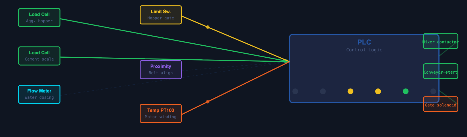
Sensors are the eyes and ears of a machine's control system. They convert physical conditions — position, weight, presence, distance, temperature — into electrical signals that the PLC can read and act on. Without sensors, automation is impossible: the machine has no awareness of its own state.
A mechanical switch actuated by physical contact with a moving part. Produces a binary signal (on/off). Used to detect end positions of travel — a gate fully open, a cylinder fully extended, a hopper door fully closed. Robust, simple, inexpensive. Fail-safe design: normally closed contacts mean a broken wire registers as a fault, not as a false "position reached" signal.
→ Conveyor belt tension arm position
→ Crane hook upper limit (prevents overwinding)
Detects the presence of an object without physical contact. Inductive types detect metal objects; capacitive types detect any material including aggregates, water, or powder. Output is a 24 V DC signal (PNP or NPN) that goes high when the target is within detection range. No moving parts — virtually unlimited switching life.
→ Count revolutions on a conveyor roller
→ Detect metal bucket position
→ Belt slip detection (rotating disk)
Converts force (weight) into an electrical signal proportional to the applied load. Uses strain gauges bonded to a metal beam — the tiny deformation of the beam under load changes the strain gauge resistance, which is measured as a voltage. Output is typically a millivolt signal amplified to 4–20 mA for PLC input. Batching accuracy depends entirely on load cell calibration.
→ Cement weigh hopper
→ Water weighing tank
→ Admixture dosing scale
Converts rotational position or speed into a digital pulse signal. An incremental encoder produces a train of pulses as the shaft rotates — the PLC counts pulses to determine position or speed. Absolute encoders report the exact angular position even after power loss. Used wherever precise positioning or speed feedback is needed.
→ Mixer speed verification
→ Conveyor belt speed measurement
→ VFD speed feedback for closed-loop control
Converts temperature to an electrical signal. RTDs (Pt100) and thermocouples are most common in industrial equipment. Used for motor winding temperature protection (trips the motor if windings overheat), gearbox oil temperature, concrete mix water temperature control, and ambient temperature compensation in weighing systems.
→ Concrete water temperature control
→ Gearbox oil temperature monitoring
→ Control panel internal temperature
The standard analogue signal format for industrial sensors and transmitters. 4 mA represents zero/minimum of the measured range; 20 mA represents full-scale. The 4 mA live-zero allows the control system to distinguish "sensor reading zero" from "signal wire broken" (which reads 0 mA). Immune to voltage noise over long cable runs.
→ Pressure transmitter (hydraulic, air)
→ Level transmitter (water, slurry tank)
→ Flow meter output
Control Systems Basics
Control Panels
A control panel (also called an electrical panel, MCC — Motor Control Centre, or distribution board) is the central hub of a machine's electrical system. It contains: the incoming supply connection and main isolator, individual circuit breakers for each motor and circuit, motor starters (contactor + overload), the PLC and its I/O modules, the 24 V DC control power supply, terminals for field wiring (sensors, actuators, remote I/O), and the HMI (Human-Machine Interface) or operator panel.
PLC — Programmable Logic Controller
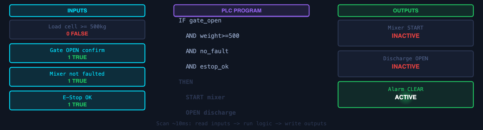
A PLC is an industrial computer designed to control machines and processes in real time. It continuously reads its input signals (sensors, switches, operator commands), executes a control programme stored in its memory, and updates its output signals (contactors, valves, indicators) — typically completing this cycle in 10–100 milliseconds.
A batching plant PLC manages the entire production sequence: open the aggregate gate → wait for target weight on load cell → close gate → start cement screw → wait for cement weight → start water fill → start mixer → count mixing time → discharge → repeat. This sequence runs automatically and consistently, regardless of operator skill.
Signal vs Power — A Critical Distinction
Control panels contain two completely separate electrical systems. Power circuits carry 400 V AC to motors — heavy cables, large contactors, substantial heat generation. Signal circuits carry 24 V DC to sensors and PLC inputs — thin cables, tiny terminals, sensitive electronics. Mixing these up causes immediate destruction of the PLC or sensor. When wiring or modifying a panel, always confirm which terminal block you are working on.
A PLC's output signal is only as good as its input signals. If a load cell is out of calibration, the PLC will control batching based on wrong weight data — the sequence will run perfectly but the concrete will be wrong. If a limit switch is stuck closed, the PLC will not know the gate failed to open and may proceed with a zero-aggregate batch. Sensor calibration and verification is maintenance for the control system, not just for the mechanical parts. This is why batching plant commissioning always includes load cell calibration verification before the first production batch.
Common Electrical Issues in Construction Equipment
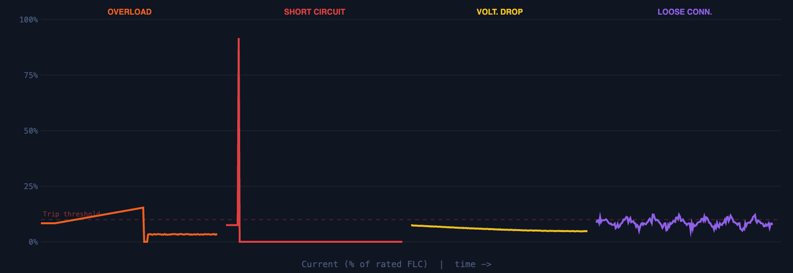
Motor draws more current than its rated FLA for a sustained period. Causes: mechanical overload (jammed mixer, blocked conveyor, bearing failure), wrong motor for the application, or supply voltage too low (motor draws more current to maintain torque).
Action: check motor current, check load, check voltage
Risk if ignored: motor winding insulation damage → rewind or replace
Direct connection between live conductors (or live to earth) with negligible resistance. Produces enormous instantaneous current — hundreds or thousands of amps. Trips the circuit breaker immediately (magnetic trip, not thermal). Caused by: insulation breakdown, cable damage, rodent damage, water ingress, or work accidents.
Action: do NOT reset repeatedly — find the fault first
Risk if unprotected: cable fires, equipment destruction
Voltage at the motor terminals is lower than supply voltage due to resistance in the cable. Common when cable runs are long (mobile equipment, remote installations) or cables are undersized. A motor receiving 360 V instead of 400 V loses significant starting torque and draws higher current — the opposite of the intended protection.
Action: measure voltage at motor terminals (not at panel)
Rule: keep voltage drop below 3–5% of supply voltage
The most common cause of unexplained electrical faults in construction equipment. Vibration loosens terminal screws over time. A loose connection has high resistance, generating heat. The heat carbonises the terminal, increasing resistance further, generating more heat — until the terminal burns or the cable arcs. Intermittent faults that come and go with temperature are almost always loose connections.
Action: thermal imaging scan of all panels annually
Prevention: torque-check all terminals at commissioning and after 100 hours
A circuit breaker that trips is doing its job. The correct response is to investigate the cause before resetting. Repeatedly resetting a tripping breaker bypasses the protection that the breaker exists to provide. If the fault is a short circuit, each reset sends another surge of fault current through the cable — potentially igniting insulation or destroying equipment. If the fault is thermal overload, each reset allows the motor to accumulate more heat damage in its windings. The message to clients is direct: a tripping breaker is a symptom, not the problem. Find the cause first.
Lesson 8 — Electrical Components Summary
| Component | Function | Key Spec | Failure Mode | Equipment Example |
|---|---|---|---|---|
| Circuit Breaker | Disconnects on overload or short circuit — protects cables | Rated current (A), breaking capacity (kA) | Trips immediately on fault — investigate before reset | Main panel breaker, individual motor MCB |
| Contactor | Electrically switches high-power loads on/off under PLC command | Rated current (A), coil voltage (24 V DC typical), mechanical life | Contacts weld closed → motor cannot stop; contacts burn → motor cannot start | Mixer motor starter, pump motor run contactor |
| Overload Relay | Protects motor from sustained overcurrent — set to motor FLA | Current range (A), trip class (Class 10, 20, 30) | Wrong setting → motor unprotected or nuisance trips | Every motor starter in a batching plant panel |
| Transformer | Steps voltage up or down; isolates control from power circuit | Primary/secondary voltage, kVA rating | Insulation failure → control circuit loss | 400 V → 24 V control transformer in panel |
| VFD | Controls motor speed by varying output frequency; soft-start | kW rating, input/output voltage, control interface | Overheating (blocked vent), harmonic interference, parameter loss | Pump speed control, conveyor speed adjustment |
| Induction Motor | Converts three-phase electrical power to rotating mechanical power | kW, voltage, FLA, RPM, IP rating, efficiency class | Bearing failure, winding insulation breakdown from overload or moisture | Mixer drum, aggregate conveyor, cement screw drive |
| Limit Switch | Binary position detection by mechanical contact | Contact form (NO/NC), current rating, IP rating | Worn actuator, water ingress, wrong calibration position | Aggregate gate open/closed, crane hook upper limit |
| Proximity Sensor | Non-contact presence detection (inductive or capacitive) | Detection range (mm), output type (PNP/NPN), supply voltage | Too far from target, wrong material type, supply voltage fault | Material level detection, belt speed monitor |
| Load Cell | Converts weight/force to proportional electrical signal | Capacity (kg), output (mV/V), IP rating, accuracy class | Overload damage, off-centre loading, calibration drift, moisture in junction box | Aggregate hopper, cement hopper, water scale |
| PLC | Executes control sequence — reads inputs, runs programme, drives outputs | I/O count, cycle time, communication protocols | Programme corruption, power supply failure, I/O module failure | Batching plant sequencer, crane anti-collision, pump station control |
- Voltage drives current; current does the work and causes the heat. Every cable, breaker, and contactor rating is fundamentally a current rating — not a voltage rating.
- Three-phase is always used for industrial motors. It delivers smooth power, self-starting motors, and higher efficiency. A site without three-phase cannot run a batching plant without a generator.
- Power circuits (400 V AC) and signal circuits (24 V DC) are separate systems. Mixing them up destroys PLCs and sensors instantly. Always verify which circuit you are working on.
- FLA is the single most important motor specification. Set the overload relay to FLA. Size the cable and contactor to FLA. Measure actual running current against FLA to diagnose problems.
- Load cell calibration is the foundation of batching accuracy. A perfect PLC programme produces wrong concrete if the load cell readings are wrong. Calibration is not a one-time event — it drifts with temperature, overload events, and mechanical changes.
- A tripping breaker is a signal — not the problem. Resetting it without investigation risks fire, equipment destruction, and injury. Find the cause first.
- Loose connections cause more unexplained faults than any other single issue. Vibration, thermal cycling, and poor initial torquing all loosen terminals. Thermal imaging of panels is one of the highest-value preventive maintenance activities available.