
What a Hydraulic System Is
A hydraulic system uses pressurised fluid — almost always oil — to transmit force from one point to another. Instead of gears, belts, or chains carrying mechanical power, a hydraulic system carries power through a fluid in hoses and pipes.
The word comes from the Greek hydro (water) and aulos (pipe). Modern hydraulic systems use mineral oil rather than water because oil lubricates the components it passes through, resists rust, and handles higher temperatures and pressures.
The fundamental idea is simple: a pump pushes oil into a confined space, building pressure. That pressure acts on a piston or motor, producing force or motion at the output. The oil is not consumed — it circulates continuously from the tank, through the pump, to the actuator, and back to the tank.
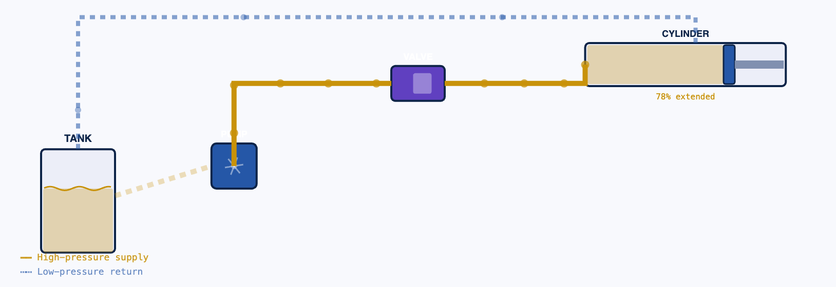
This is the most important thing to understand about hydraulic systems. Oil is not fuel — it is not consumed. A hydraulic system that is losing oil is leaking. A system that requires frequent top-ups has a leak that has not been found yet. Every litre of oil that leaves the system eventually becomes a contamination problem — on the ground, on components, in the environment.
Why Use Hydraulics Instead of Mechanical Systems
For many applications, hydraulics are simply the best engineering solution. Understanding why helps you explain product decisions to clients and engineers.
Hydraulic systems produce enormous force from very compact components. A hydraulic cylinder the size of a bottle can generate hundreds of tonnes of force. No mechanical system — gears, screws, levers — can match this force-to-size ratio.
A hydraulic cylinder can be stopped at any position along its stroke by closing a valve. It holds that position under load without any additional energy input — the incompressible oil traps the load in place. Mechanical systems require brakes or locks to hold position.
By controlling flow rate (how fast oil moves) and pressure (how hard oil pushes), you independently control the speed and force of the actuator. No clutches, gearboxes, or complex mechanical linkages needed.
A simple pressure relief valve limits the maximum force a hydraulic system can generate, regardless of how hard the pump works. This provides built-in overload protection that mechanical systems achieve only with complex slipping clutches or shear pins.
Mechanical systems (gears, belts, chains) win at efficiency over long power transmission paths — a gearbox is 96% efficient, a hydraulic circuit typically 75–85%. Hydraulics win at force density, flexibility of routing (a hose can go anywhere a pipe can), easy reversibility, and position holding under load. This is why cranes use hydraulics for their booms and jibs but gears in their hoist mechanisms.
Basic Principles — Pressure, Flow, and Force
Pressure
Pressure is force per unit area. In hydraulic systems, it is measured in bar (1 bar = 100,000 Pa ≈ atmospheric pressure). Most construction hydraulic systems operate at 200–350 bar. The pump creates pressure by resisting the flow of oil — pressure builds up because the oil has nowhere to go.
Mental model: Pressure in a hydraulic system is like pressure in a sealed water balloon. The balloon does not generate the pressure — your hand squeezing it does. The pump is the hand. The oil is the water. The pressure exists throughout the system simultaneously.
Flow
Flow rate is how much oil moves through the system per unit time — measured in litres per minute (L/min). Flow rate determines speed: more flow into a cylinder means the piston moves faster. A pump that produces more flow runs actuators faster, but does not necessarily produce more force.
Force = Pressure × Area (Pascal's Law)
Pascal's Law: pressure applied to a confined fluid transmits equally in all directions throughout the fluid. The force produced at any surface equals the pressure multiplied by the area of that surface.
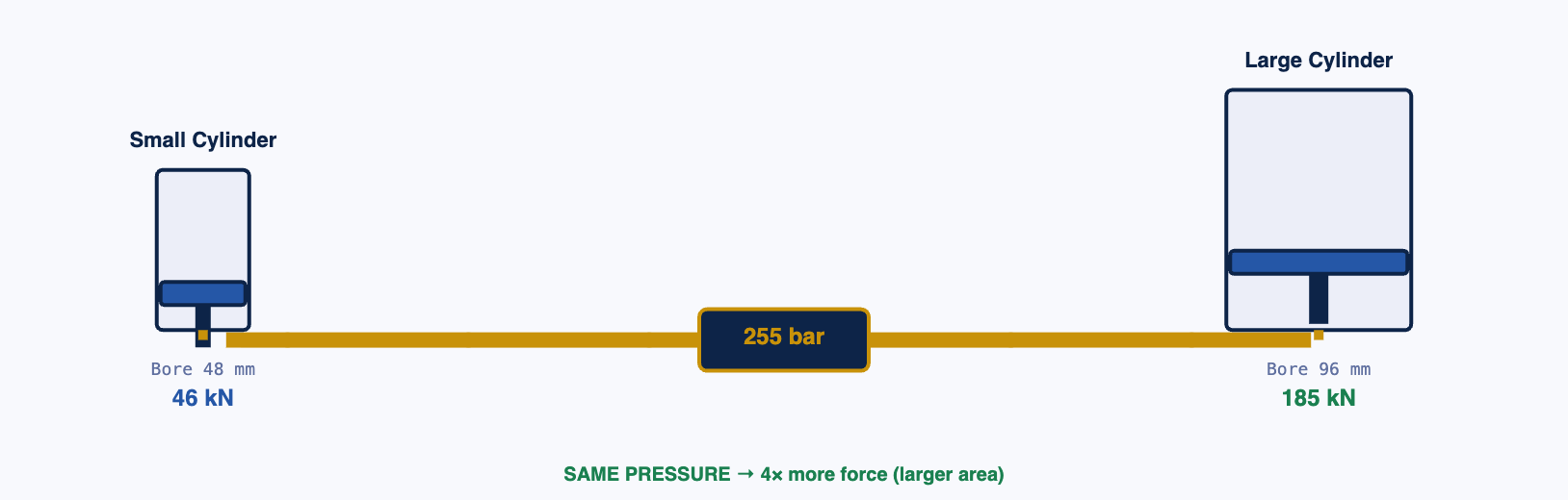
When a client asks why a small hydraulic cylinder in a pipe bender can bend heavy-gauge steel pipe, the answer is area multiplication. The pump generates 300 bar throughout the circuit. That same 300 bar acts on a cylinder with a large bore — say 150 cm² piston area. Force = 300 × 150 × 0.1 = 4,500 kN = 450 tonnes. The pump itself is a modest electric motor. The force amplification comes entirely from the area of the piston.
Main Hydraulic Components
Every hydraulic system — from a simple cylinder to a complex crane — contains the same fundamental components. Understanding each one allows you to trace a fault, explain a specification, or describe why a particular component matters to a client.
Converts mechanical power (from a motor or engine) into hydraulic power by pushing oil into the system. The pump does not create pressure — it creates flow. Pressure builds up as a consequence of the flow meeting resistance. Types: gear pumps (simple, robust), piston pumps (high efficiency, variable displacement), vane pumps (quiet, medium pressure).
→ Axial piston pump on a crane hydraulic system
→ Variable displacement pump on an excavator
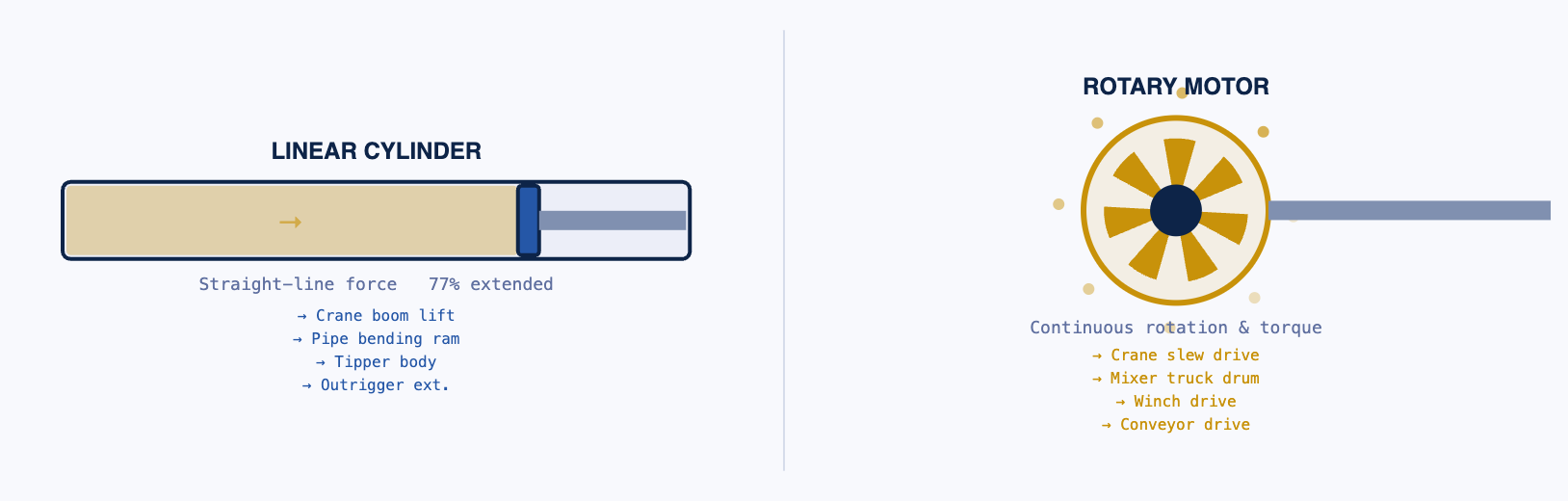
Converts hydraulic pressure into linear force and motion. Oil enters one side of the cylinder and pushes the piston. The piston rod extends or retracts. The force produced equals pressure × piston area. Double-acting cylinders (oil on both sides) can push and pull. Single-acting cylinders (oil on one side, spring return) only push.
→ Pipe bending machine ram
→ Tipper truck body lift
→ Formwork stripping actuator
Converts hydraulic pressure into rotational motion — the opposite of a pump. Used wherever continuous rotation is needed but electric motors are impractical. Can produce very high torque at low speed in a compact size. Reversible by reversing flow direction. Found in winches, crane slew rings, conveyor drives, and mixer drums on some machines.
→ Concrete mixer truck drum drive
→ Winch motor
→ Conveyor drive on mobile plant
Directional control valves route oil to one side or another of an actuator — they make the cylinder extend or retract. Pressure relief valves limit maximum system pressure and open to dump oil back to tank if pressure exceeds the set limit (safety). Flow control valves restrict oil flow to control actuator speed. Check valves allow flow in one direction only, preventing backflow.
→ Relief valve protecting cylinder from overload
→ Flow control slowing a cylinder to safe speed
→ Check valve holding boom position
Stores the hydraulic oil, allows it to cool, and lets air bubbles and particles settle out before the oil recirculates. Correctly sized reservoirs hold 2–3 times the pump's flow rate per minute, giving oil enough dwell time to cool and deaerate. A sight glass or dipstick shows oil level. A breather filter prevents contaminated air entering as oil level rises and falls.
→ Batching plant gate actuator reservoir
→ Hydraulic power pack on a pipe bender
Remove solid particles from the oil. Contamination — metal particles from wear, dust, water — is the leading cause of hydraulic system failure. Filters are placed at the pump inlet (suction filter, coarse), in the return line (return filter, medium), and sometimes in high-pressure lines (pressure filter, fine). Filter element condition is indicated by a differential pressure gauge or bypass indicator.
→ Suction strainer in reservoir
→ High-pressure filter on servo systems
→ Breather filter on reservoir cap
How a Hydraulic System Works — The Full Cycle
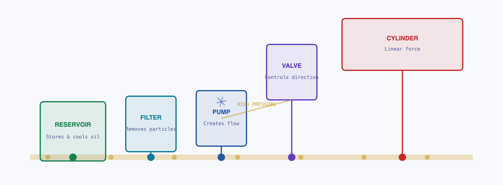
Tracing oil through a complete hydraulic cycle is the best way to understand how the system functions. Every hydraulic system in every machine follows this same path.
Cool, filtered oil sits at low pressure, ready to be drawn by the pump.
Draws oil from tank and pushes it into the high-pressure line, building system pressure.
Operator or control system commands the directional valve. Oil is routed to the actuator's extend or retract port.
Oil pressure acts on the piston area, generating force. Cylinder extends, lifting the load. Displaced oil exits from the other side.
Return oil passes through the return filter, releases heat in the reservoir, and the cycle repeats.
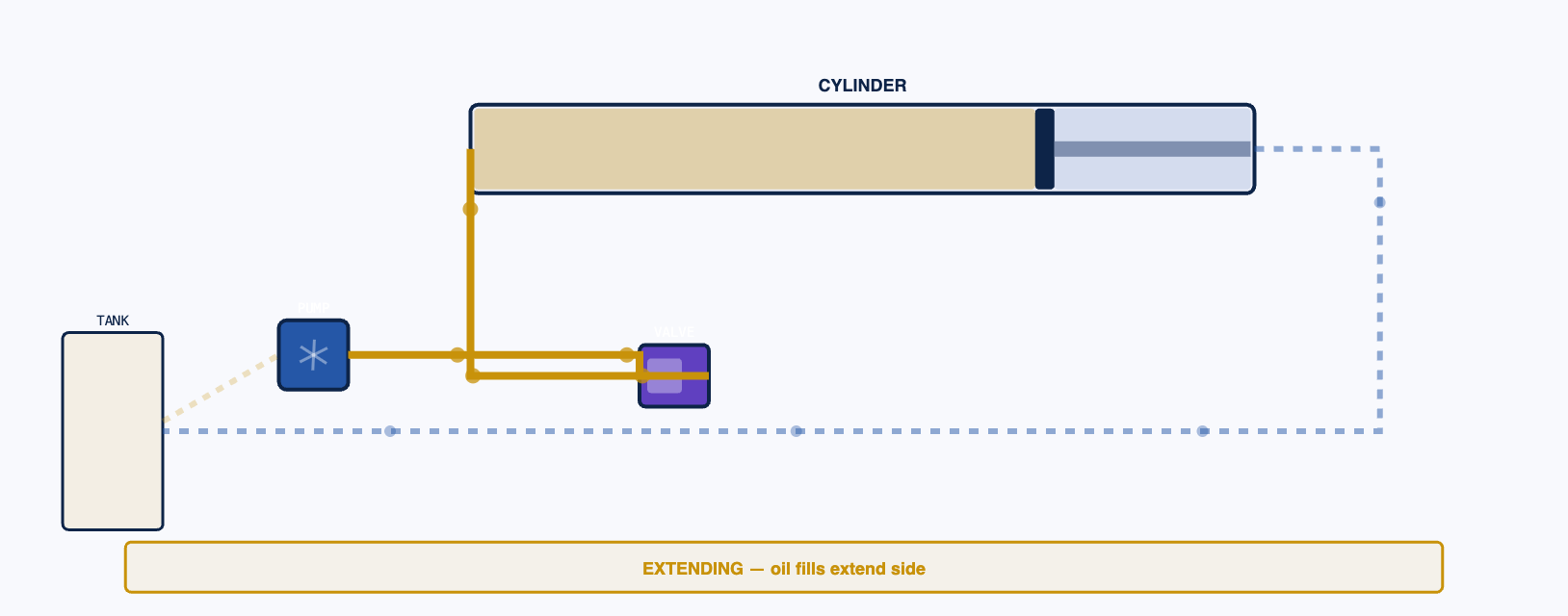
An operator reports:
"The crane boom lifts fine but won't lower on its own — it only lowers if I force
it."
This describes a counterbalance valve (load-holding valve) that is set too high, or a
blocked return line on the retract side. The cylinder can extend (oil pressure lifts the
boom) but cannot retract freely because the return oil cannot flow back at the pressure
available. It is not a pump problem — the pump is working. It is a valve or line
restriction on the return circuit. This is how you distinguish between supply-side and
return-side faults.
Types of Hydraulic Actuators
An actuator is the output device that converts hydraulic pressure and flow into mechanical work. There are two fundamental types.
Converts oil pressure into straight-line force and motion. The piston rod extends and retracts. Used wherever you need to push, pull, lift, clamp, or bend in a straight line.
Double-acting: Oil pressurises both extend and retract sides. Full force in both directions. Standard for most construction applications.
Single-acting: Oil pressurises only the extend side. A spring returns the rod when pressure releases. Used for clamping or where gravity returns the load.
→ Pipe bending ram
→ Tipper body lift
→ Formwork stripping
→ Outrigger extension
Converts oil pressure into continuous rotation. Used wherever sustained torque and rotation are needed. Hydraulic motors can deliver enormous torque at low speed in a very compact package — far more than equivalently-sized electric motors.
Gear motors: Simple, robust. Piston motors: High efficiency, variable speed. Vane motors: Smooth torque at medium speed.
→ Concrete mixer truck drum
→ Winch drive
→ Drill rig rotation
→ Conveyor belt drive
Common Issues in Hydraulic Systems
Hydraulic systems fail in predictable ways. Understanding these failure modes makes you a far more credible adviser to clients — and helps you explain why quality components and scheduled maintenance matter.
💧 Leaks
The most visible and most common hydraulic problem. External leaks (oil visible on the machine or ground) occur at fittings, hose ends, rod seals, and static O-rings. Internal leaks (oil bypasses a piston seal inside a cylinder) cause loss of force and drift — a cylinder that slowly retracts under load without any command.
→ Cylinder drifting downward under held load
→ System needs frequent oil top-up
→ Causes: worn seals, damaged rod, loose fittings, over-pressure events
📉 Pressure Loss
The system cannot reach its rated working pressure, so actuators move slowly or cannot lift rated loads. Causes: worn pump (internal leakage — oil bypasses back to inlet), relief valve set too low or stuck open, or severe internal cylinder seal leakage. A pressure gauge at the pump outlet identifies whether this is a pump or downstream issue.
→ Cannot lift rated load
→ Pump running hot under normal load
→ Causes: pump wear, wrong relief valve setting, cylinder bypass
🌡 Overheating
Hydraulic oil above 80°C begins to degrade rapidly. Above 90°C, seal materials harden, viscosity drops, and oil oxidises. Overheating occurs when the system generates more heat than the reservoir and oil cooler can dissipate. Causes: undersized reservoir, blocked cooler, excessive pressure drop across valves, continuous relief valve cracking (system fighting itself).
→ Oil smells burnt
→ Seals swelling or weeping
→ Causes: blocked cooler, excessive relief valve bypass, undersized tank
🔴 Contamination
The leading cause of hydraulic component failure. Particles as small as 10 microns (invisible to the naked eye) scratch valve spools, score pump bores, and embed in seals. Water contamination (condensation, rain ingress) causes corrosion and oil emulsification. A clogged filter that is bypassed introduces contaminants directly into the pump and valves.
→ Causes: dirty top-up procedure, damaged breather filter, worn components shedding particles
→ Consequence: accelerated wear across all components simultaneously
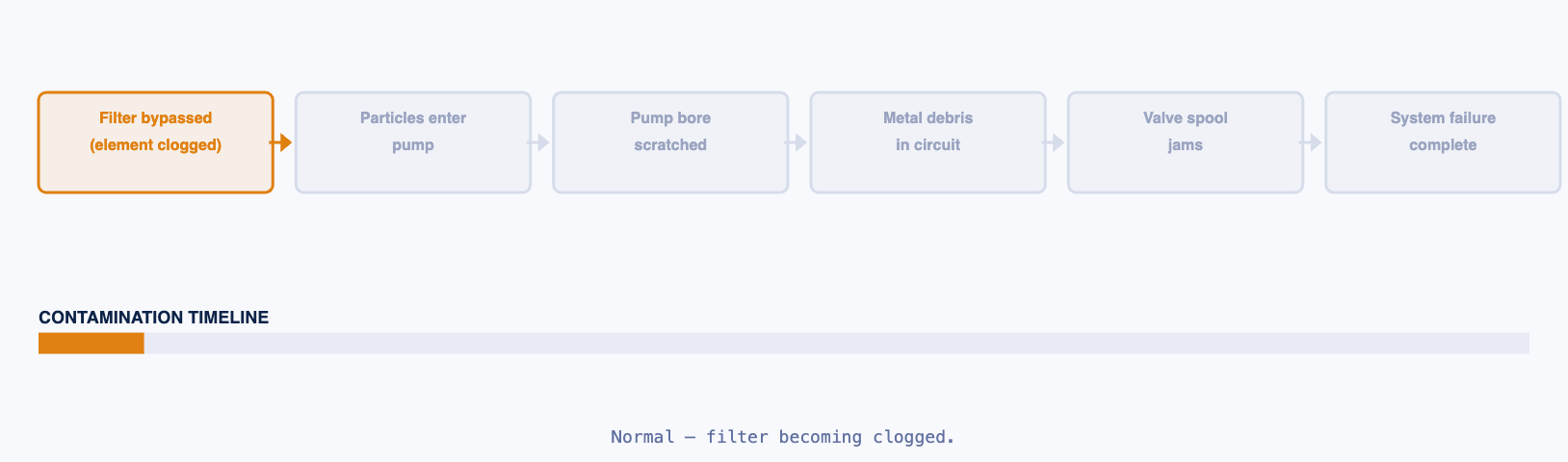
Hydraulic oil cleanliness is rated using the ISO 4406 standard (e.g. 18/16/13). Each number represents the count of particles per millilitre above a given size. Modern servo valves and piston pumps require ISO 16/14/11 or cleaner — that is 10 times cleaner than oil visible to the naked eye. Using the wrong grade of filter, skipping filter changes, or topping up with unfiltered oil from an open container can take a clean system to a contaminated one in one maintenance session. This is why sealed, labelled oil containers and dedicated fill equipment matter.
Basic Fluid Concepts
Viscosity
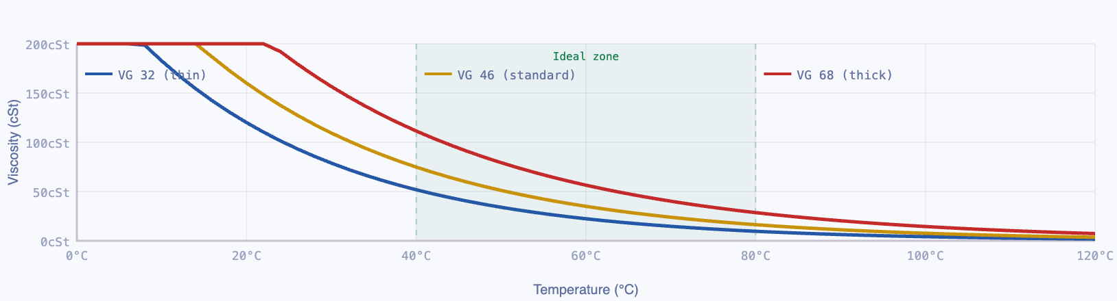
Viscosity is the measure of how thick or thin a fluid is — its resistance to flow. Hydraulic oil viscosity is rated in ISO VG (Viscosity Grade). VG 32 is thin (flows easily), VG 68 is thicker. The correct viscosity for a machine depends on operating temperature and the clearances in its pumps and valves.
Too thin: Oil bypasses internal clearances — loss of efficiency, reduced lubrication film, increased wear and heat generation. Too thick: Oil does not flow fast enough — high pressure drops at the pump inlet, cavitation damage, sluggish actuator response in cold conditions. Using the wrong viscosity grade is a maintenance error that can destroy a pump within weeks.
Incompressibility
Liquids, unlike gases, cannot be meaningfully compressed. This property is what makes hydraulics work. When you push on one end of a sealed column of oil, the force transmits immediately to the other end — no energy is stored or lost to compression. This is why a hydraulic cylinder holds position under load when its valves are closed. The oil trapped in the cylinder cannot compress and escape, so the load cannot move.
In practice, oil is slightly compressible at very high pressures (above 300 bar), and dissolved air in oil causes spongy, inconsistent actuator behaviour. Air in a hydraulic system is both a performance problem and an overheating risk (air compresses and generates heat).
Temperature Effects
Temperature affects viscosity, seal integrity, and oil life simultaneously. Cold start-up with thick oil can starve the pump of oil, causing cavitation — the pump draws vacuum on its inlet side, oil vapour bubbles form and implode violently on the high-pressure side, eroding pump internals within hours. Warm-up procedures for hydraulic equipment in cold conditions (allow the oil to circulate at low load for several minutes before applying full pressure) exist specifically to prevent this.
A hydraulic oil temperature gauge tells you more about the health of a system than almost any other instrument. Normal operating temperature: 40–70°C. Consistent operation at 80°C+ shortens oil life by half for every 10°C increase. If a system is running hot under loads it previously handled without overheating, something has changed: a blocked cooler, a partially failed pump working harder than it should, a valve partially bypassing, or a load that is being held under continuous pressure for far longer than the system was designed for.
Lesson 7 — Hydraulic Components Summary
| Component | Function | Key Spec to Know | Failure Mode | Equipment Example |
|---|---|---|---|---|
| Hydraulic Pump | Creates flow — draws oil from tank and pushes it into the pressure line | Flow rate (L/min), max pressure (bar), displacement (cc/rev) | Wear → internal bypass → pressure loss, overheating | Crane boom power pack, pipe bender power unit |
| Hydraulic Cylinder | Converts pressure + area into linear force and movement | Bore diameter (mm), stroke (mm), max pressure rating (bar) | Seal wear → internal/external leakage → drift under load | Crane boom lift, tipper body, pipe bending ram |
| Hydraulic Motor | Converts pressure + flow into continuous rotation and torque | Displacement (cc/rev), max torque (N·m), max pressure (bar) | Wear → bypass → loss of torque and speed | Crane slew drive, mixer truck drum, winch drive |
| Directional Valve | Routes oil to extend or retract the actuator — controls direction of motion | Nominal flow (L/min), spool type (4/3, 4/2), actuation (manual, solenoid, pilot) | Spool sticking from contamination, worn seals → drift | All crane, press, and cylinder control circuits |
| Pressure Relief Valve | Limits maximum system pressure — opens to tank when set pressure is reached | Set pressure (bar), flow capacity (L/min) | Stuck open → no pressure; stuck closed → overpressure damage | Every hydraulic circuit — the safety device |
| Flow Control Valve | Restricts flow to control actuator speed — independent of load pressure | Compensated vs uncompensated, flow range (L/min) | Blocked orifice → no movement; worn → loss of speed control | Crane lowering speed, cylinder creep prevention |
| Check Valve | Allows flow one direction only — prevents backflow and holds load | Cracking pressure (bar), flow rate (L/min) | Contamination holds valve open → load drifts | Load-holding circuits, pump outlet, circuit isolation |
| Reservoir (Tank) | Stores oil, allows cooling and deaeration, permits level monitoring | Volume (litres — should be 2–3× pump flow/min), material, breather specification | Undersized → overheating; contaminated breather → dirty oil | Every hydraulic power pack and machine |
| Return Filter | Removes particles from oil returning to tank before recirculation | Micron rating (β-ratio), bypass pressure setting, element change interval | Bypass indicator tripped → unfiltered oil entering system | Every hydraulic circuit — the contamination barrier |
- Pressure controls force. Flow controls speed. These are independent. Quoting a pump by kW alone tells a client nothing useful — you need flow rate at rated pressure.
- Force = Pressure × Area. A large cylinder bore at moderate pressure produces more force than a small cylinder at high pressure. Bore size is the primary force specification for any cylinder application.
- Oil circulates, it is not consumed. Any system requiring regular oil top-up has an unidentified leak. Find the leak before adding oil.
- Contamination is the leading cause of hydraulic failure — not overload, not wear-out, not design error. Clean oil, clean fill procedures, and functioning filters extend system life by orders of magnitude.
- Oil temperature tells you system health. A system consistently running hotter than usual is working harder than it should — something has changed internally.
- Viscosity must match the application and operating temperature. Wrong grade oil causes either bypass and heat (too thin) or cavitation and sluggishness (too thick). Check the OEM specification before recommending or approving an oil change.
- A cylinder holds position because oil is incompressible. If a cylinder drifts under a held load, oil is bypassing somewhere — either internal piston seals or the directional valve spool. This is a precision seal problem, not a pressure problem.