
What a Mechanical System Is
Every machine you sell — whether a batching plant mixer, a crane hoist, or a concrete pump — is a mechanical system. All mechanical systems follow the same fundamental model: Input → Transmission → Output.
Input is the energy source: an electric motor or a diesel engine. It converts electrical or chemical energy into rotational mechanical energy.
Transmission is everything in between: shafts, gears, couplings, belts, chains, gearboxes. It takes the rotation from the input and delivers it to the output — changing speed, torque, or direction along the way.
Output is what the machine actually does: a mixer drum turning, a crane hook rising, a pump impeller spinning, a conveyor belt moving.

When you look at any machine, mentally trace the power flow. Where is the input? How many transmission stages are between it and the output? Every stage introduces losses. Every component is a potential failure point. This is how a maintenance engineer thinks when diagnosing a problem — and how you should think when explaining performance to a client.
In complex machines, the same input can drive multiple outputs simultaneously. A batching plant has one main electrical supply feeding multiple motors: the aggregate conveyor, the cement screw, the mixer drum, the water pump, and the control panel. Each path is an independent mechanical system branching from the same power input.
Types of Power Sources
Every mechanical system begins with a power source. In construction equipment, you will encounter two: electric motors and diesel engines. Understanding the differences matters for site planning, equipment selection, and client conversations.
Converts electrical energy into rotational mechanical energy. The most common power source in fixed or semi-fixed construction equipment: batching plants, conveyor systems, mixers, pumps, and compressors.
Key characteristics: highly efficient (92–97%), low maintenance, consistent speed under varying loads, requires electrical supply infrastructure.
Starting surge: When an electric motor starts, it draws 5–7× its rated current for a brief moment to overcome rotor inertia. This is why batching plant electrical panels include star-delta starters or soft-starters for large motors — to protect both the motor and the site's electrical supply from the startup spike.
Converts chemical energy (fuel combustion) into rotational mechanical energy via pistons, crankshaft, and flywheel. The only option for mobile or remote equipment: mobile cranes, mobile batching plants, concrete mixer trucks, excavators, and generators.
Key characteristics: 35–45% thermal efficiency (most energy lost as heat), produces high torque at low RPM, self-contained power, requires fuel management and more maintenance than electric.
Torque curve: Diesel engines produce their peak torque at relatively low RPM — typically 1200–1800 RPM — which is why they suit heavy-pulling applications like cranes and compactors. They must run at a specific RPM to deliver rated power.
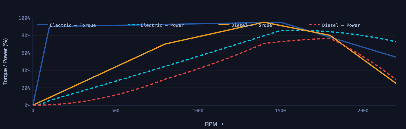
When a contractor specifies a batching plant with 150 kW total connected load, they need a transformer or generator capable of handling both the steady running load and the startup surges. A generator sized only to match running load will trip every time a large motor starts. This is a real commissioning problem — and the conversation you should be having with the client's electrical team before equipment delivery, not after.
Rotational vs. Linear Motion
All power sources produce rotational motion — a shaft spinning in a circle. But many machine outputs require linear motion — something moving in a straight line: a crane hook going up, a hydraulic cylinder extending, a piston pumping.
Mechanical systems convert between these two motion types constantly. Understanding which type of motion each component produces and which it requires explains why a machine is designed the way it is.
Measured in RPM (revolutions per minute). Produced by motors and engines. Transmitted by shafts, gears, belts, and chains. Most efficient form of mechanical power transmission over distance.
→ Gearbox input/output
→ Mixer drum rotating
→ Pump impeller spinning
→ Conveyor drive pulley
→ Fan blades
Measured in m/s or m/min. Required by many machine outputs. Produced by converting rotational motion via wire ropes, rack-and-pinion, crank-slider mechanisms, or hydraulic actuators fed by rotary pumps.
→ Hydraulic cylinder extending
→ Pipe bending machine arm
→ Conveyor belt surface moving
→ Vibrator compacting concrete
→ Piston pump stroke
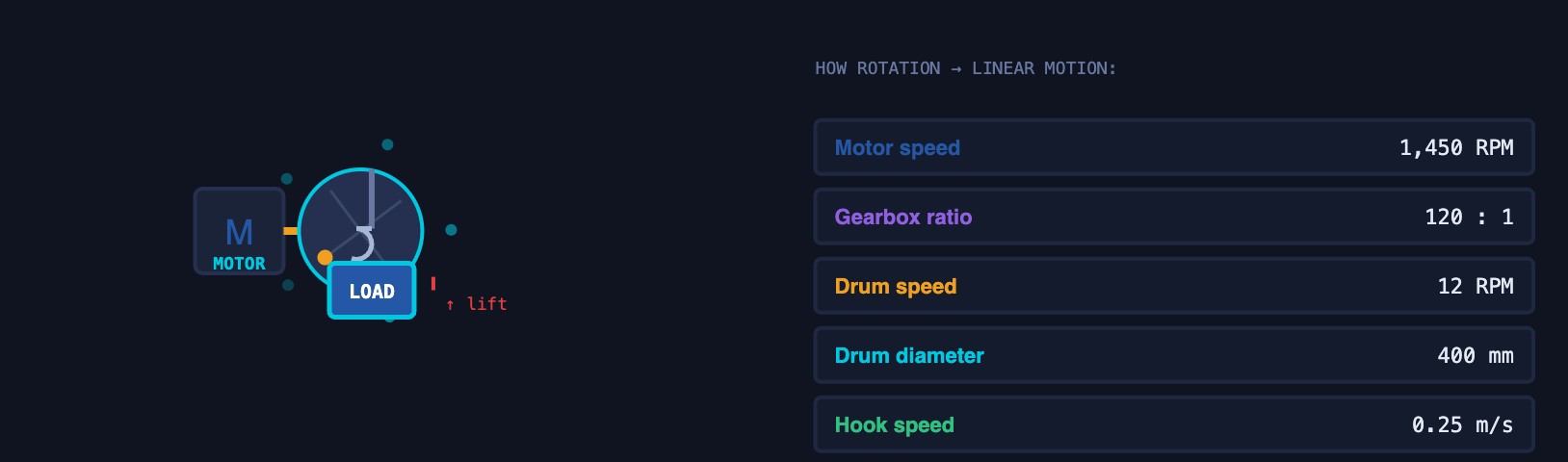
A crane hoist motor turns at 1,450 RPM. The wire rope drum might rotate at 12 RPM to produce a safe hook speed of 0.25 m/s. Between the motor and the drum sits a gearbox with a reduction ratio of roughly 120:1. Understanding this chain — motor RPM → gearbox reduction → drum RPM → hook speed — is how you explain why a higher-powered motor produces a faster or heavier lift, not both simultaneously.
Main Power Transmission Components
Between the power source and the output, a machine's transmission consists of components that carry, redirect, convert, and control power. Each component has a specific role — and a specific failure mode.
A rotating rod that transmits torque from one component to another. The fundamental carrier of rotational power. Shafts must be strong enough to handle the torque without twisting, stiff enough not to deflect under load, and balanced to avoid vibration at high speed.
→ Gearbox input/output shafts
→ Pump drive shaft
→ Mixer gearbox shaft
Connects two shafts together to transmit torque while accommodating small misalignments. Rigid couplings lock two shafts together precisely. Flexible couplings (jaw, disc, elastomeric) absorb vibration and tolerate minor angular and parallel misalignment between motor and driven machine.
→ Motor-to-gearbox coupling
→ Conveyor drive coupling
→ Flexible jaw coupling on mixers
Toothed wheels that mesh together to transmit torque between shafts. Gears change rotational speed and torque simultaneously — if one gear drives a larger gear, speed decreases and torque increases by the same ratio. Gears are enclosed in gearboxes with oil lubrication and can achieve any required reduction ratio.
→ Mixer gearbox (high-torque output)
→ Pump gearbox
→ Worm gear drives
A belt runs over two or more pulleys to transmit power between shafts that are not in direct contact. Simple, low-cost, and self-damping (absorbs shock loads). Belts slip under extreme overload, which protects the driven machine. V-belts are standard; flat belts and synchronous (timing) belts are used in specific applications.
→ Conveyor head pulley drive
→ Compressor drives
→ Aggregate screener drives
A roller chain engages toothed sprockets to transmit power without slip. More precise than belts — the chain cannot slip off the teeth, so the speed ratio is exact. Heavier and requires lubrication but handles higher loads. Used where a precise speed ratio matters or where belts would slip under the load.
→ Aggregate conveyor drive
→ Batching plant hopper gates
→ Industrial machinery drives
Support rotating shafts, allow them to spin freely, and carry radial and axial loads. Without bearings, shafts would simply wear themselves out against the housing. Ball bearings handle lighter loads at high speed. Roller bearings handle heavy radial loads. Thrust bearings carry axial (end) forces.
→ Gearbox output shaft bearings
→ Conveyor roller bearings
→ Crane sheave bearings
In the field, couplings are often ignored until they fail. A flexible coupling between a motor and pump is the machine's vibration absorber and misalignment compensator. When the rubber element inside a jaw coupling deteriorates, the metal spiders start to contact directly, vibration increases, and the motor and pump bearings begin to take abnormal loads. Coupling inspection and replacement on schedule is one of the cheapest forms of machine life extension available.
Gear Systems — The Speed-Torque Trade-Off
Gears are the most powerful tool in mechanical engineering for matching a motor's output to a machine's requirement. A motor produces a specific speed and torque at its rated power. The machine it drives almost never requires that exact combination. The gearbox bridges the gap.
The fundamental rule: in a gearbox, power is nearly constant. Speed and torque trade against each other. Reduce speed by a factor of 5 and torque increases by a factor of 5 (minus efficiency losses). This is why a small, high-speed motor can drive a massive, slow-turning mixer drum through a large gearbox.

Types of Gears Used in Construction Equipment
Teeth parallel to shaft axis. Simple, efficient, but noisy. Used in most industrial gearboxes where noise is not critical.
Teeth at an angle to shaft axis. Quieter and stronger than spur gears. Standard in modern crane and mixer gearboxes. Generate axial thrust loads requiring thrust bearings.
A worm (screw) drives a worm wheel. Achieves very high reduction ratios (up to 100:1) in a compact package. Self-locking in many configurations. Lower efficiency (50–90%). Common in hoist drives and conveyors.
A maintenance engineer asks:
"The mixer is turning slower than it should and the motor is getting very hot. Can this
be a gearbox issue?"
The answer: almost certainly yes. A gearbox with worn or broken teeth, low oil level, or
failed bearings creates increased resistance that slows the output shaft. The motor tries
to compensate by drawing more current — which produces more heat. The motor's thermal
protection may then trip, causing apparent motor failures that are actually downstream
gearbox problems. This is why gearbox oil level checks are the first maintenance step, not
the last.
Bearings — Where Machines Live and Die
Bearings are the components that allow rotating shafts to spin within a stationary housing. They carry the weight of shafts, gears, and loads — the radial load (perpendicular to the shaft) — as well as axial loads (along the shaft axis from gear thrust or belt tension). Without bearings, a shaft would grind directly against the machine housing within seconds.
Rolling elements are balls. Handles moderate radial and axial loads. Very common in motors, pumps, and light-duty conveyors. Quiet, efficient, available in sealed versions.
Rolling elements are cylinders or tapered rollers. Handles heavy radial loads and significant axial loads. Used in gearboxes, crane sheaves, heavy conveyors, and mixer drums.
Specifically designed to carry axial (end-thrust) loads. Used wherever a helical gear, bevel gear, or screw thread creates axial force along the shaft. Worm gearboxes always have thrust bearings.
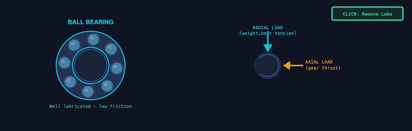
Bearing failure is the most common cause of unplanned machine downtime in construction equipment. It almost always begins with one of three causes: insufficient lubrication (oil or grease starvation), contamination (dirt, water, concrete dust entering the bearing), or overload (running a machine consistently above its rated capacity). The warning signs are: rising operating temperature at the bearing housing, increasing vibration (felt or measured), and a characteristic high-pitched whine or grinding noise. By the time noise is clearly audible, the bearing has already suffered significant damage. Vibration analysis at scheduled intervals catches this weeks before noise appears.
Losses and Efficiency in Mechanical Systems
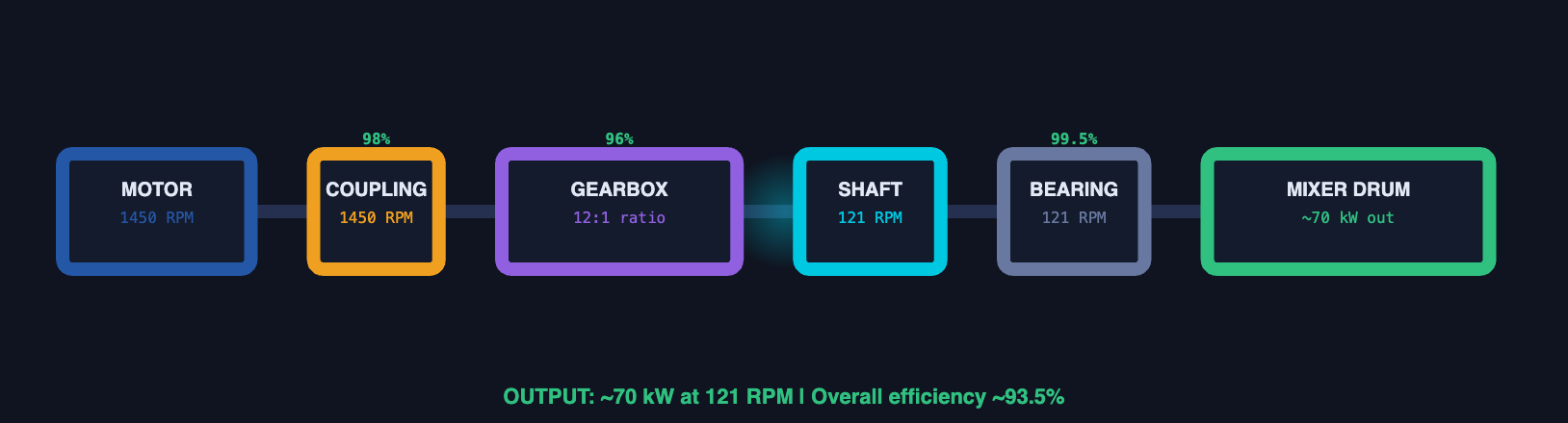
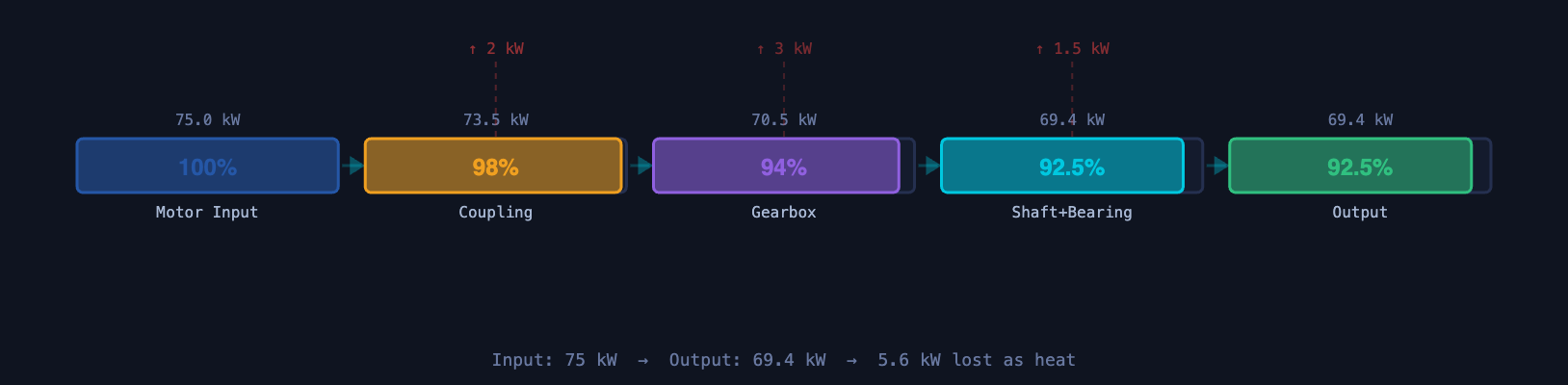
No mechanical transmission is 100% efficient. Every component between the power source and the output absorbs some energy and converts it to heat. The total efficiency of a drivetrain is the product of each component's individual efficiency — losses compound.
Friction
Every surface contact produces friction: gear teeth meshing, bearing races rolling, belt surfaces flexing, seals rubbing. Proper lubrication reduces friction dramatically — the difference between a well-lubricated gearbox at 96% efficiency and a dry one at 60% efficiency represents enormous heat generation and rapid component destruction.
Heat
Heat is the final destination of all mechanical losses. A gearbox oil that should run at 60–80°C running at 110°C is losing significantly more power than designed. High oil temperature means accelerated oxidation of the oil, reduced viscosity (thinner oil = thinner film = more metal contact = more wear), and potential seal damage. Oil temperature is one of the most informative single measurements in a gearbox.
Misalignment
When a motor shaft and a pump shaft are not perfectly aligned — either parallel (offset) or angular (tilting toward each other) — the coupling between them is forced to flex every revolution. This creates cyclic stress in the coupling, generates heat, increases bearing loads, and can cause shaft fatigue. Misalignment is the single most preventable cause of premature bearing and coupling failure in the field.
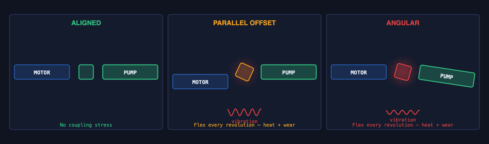
Modern pump and motor installations specify laser alignment after installation, with tolerances typically below 0.05 mm for parallel offset and 0.05°/100mm for angular misalignment. Laser alignment services are often included in premium equipment commissioning packages. When a client asks why their pump is consuming more power than specified and running hot, the first question should always be: "When was the alignment last checked?" Thermal expansion during operation shifts equipment off its cold alignment baseline — which is why hot alignment checks exist.
Basic Failure Points in Mechanical Systems
Mechanical systems fail in predictable ways. Every failure mode has a root cause, early warning signs, and a consequence if ignored. Understanding these makes you a better advisor to clients and helps you explain why preventive maintenance and genuine spare parts matter.
⚙ Wear
The gradual removal of material from surfaces in contact under load and motion. Wear is normal — every machine is designed with a wear life — but accelerated wear shortens that life dramatically. Causes: insufficient lubrication, wrong lubricant viscosity, abrasive contamination (concrete dust, sand), or running above rated load.
→ Bearing race pitting
→ Mixer blade erosion
→ Chain elongation from pin wear
→ Belt groove wear on pulleys
📐 Misalignment
Shafts that are not aligned with their mating components impose cyclic bending loads on every revolution. Even 0.2 mm of offset in a pump running at 1,450 RPM means the coupling flexes 24 times per second — 87,000 times per hour. Misalignment fails couplings, bearings, and eventually shafts through fatigue.
→ Rapid bearing wear
→ Shaft fatigue cracks
→ Seal leaks (from shaft deflection)
→ High vibration readings
🛢 Lubrication Failure
The leading cause of bearing and gear failure. Lubrication failure includes: no lubricant (forgotten during maintenance), wrong lubricant (wrong viscosity or type), contaminated lubricant (water, concrete dust, metal particles), or degraded lubricant (overheated, oxidised, wrong change interval). Metal-to-metal contact follows within minutes to hours.
→ Gear tooth scuffing and spalling
→ Rapid temperature rise
→ Chain seizing on sprockets
→ Worm gear galling
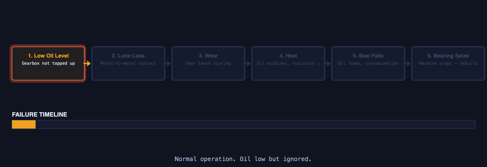
When a client replaces a failed bearing with a cheaper non-genuine part, the dimensional tolerance may be slightly different. A bearing outer race that fits loosely in its housing will creep — rotate slightly with the shaft instead of staying stationary. This abrades the housing bore, widens it, and the next bearing will fit even more loosely. The housing is then destroyed and requires machining or full component replacement at 10–50× the cost of the original genuine bearing. The same logic applies to gearbox oil viscosity grades, coupling elements, and belt cross-sections. Every specification in a maintenance manual is there because something failed when the specification was ignored.
Train yourself to notice: oil stains below gearboxes or bearings (seal failure from misalignment or wear). Belt dust accumulating below drive covers (belt slipping or glazing). Unusual vibration felt by hand on motor or gearbox housings (bearing or alignment issue). Abnormal noise — whine, growl, or knock — from any rotating component. Coupling guards that rattle (coupling element worn). Warm bearing housings when surrounding temperature is ambient (lubrication failure). Any of these is an early warning that something is consuming more energy than it should and will eventually fail.
Lesson 6 — Transmission Components Summary
| Component | Function | What It Changes | Failure Mode | Equipment Example |
|---|---|---|---|---|
| Electric Motor | Converts electrical energy to rotation | Input power source | Winding failure, bearing failure, overheating from overload | Batching plant mixer, conveyor drive, pump drive |
| Diesel Engine | Converts fuel to rotation | Input power — mobile equipment | Fuel system, cooling, injection, wear | Mobile crane, transit mixer, generator set |
| Shaft | Carries torque between components | Transmits rotation unchanged | Fatigue fracture from misalignment or overload | Motor-to-gearbox shaft, conveyor drive shaft |
| Coupling | Connects two shafts — tolerates misalignment | Absorbs vibration and angular/offset error | Rubber element wear, metal-to-metal contact, fatigue | Motor-to-pump, motor-to-gearbox connections |
| Spur/Helical Gears | Changes speed and torque ratio | Speed ÷ ratio, Torque × ratio | Tooth wear, pitting, scuffing from lubrication failure | Crane hoist gearbox, mixer reduction gearbox |
| Worm Gear | High ratio reduction in compact space | Up to 100:1 reduction, self-locking | Wear, scuffing, low efficiency heat generation | Hoist drives, conveyor drives, gate actuators |
| V-Belt & Pulley | Transmits power without direct shaft contact | Speed ratio by pulley diameter, slips on overload | Glazing, cracking, misalignment wear, slip | Compressor drives, aggregate screener drives |
| Chain & Sprocket | Positive drive — no slip | Exact speed ratio by tooth count | Elongation from pin wear, corrosion, dry running | Cement screw drive, aggregate conveyor drive |
| Ball Bearing | Supports shaft radially and axially | Allows rotation, carries load to housing | Fatigue pitting, contamination, lubrication starvation | Motor shaft, pump shaft, light conveyor rollers |
| Roller Bearing | Supports heavy radial loads on shafts | Handles higher loads than ball bearings | Spalling, misalignment damage, contamination | Gearbox shafts, crane sheaves, mixer drum support |
Power Source Comparison
| Property | Electric Motor | Diesel Engine |
|---|---|---|
| Efficiency | 92–97% | 35–45% |
| Maintenance Frequency | Low — bearings, brushes | High — oil, filters, injectors, cooling |
| Torque at Startup | High (with VFD or DOL) | Low — builds with RPM |
| Speed Control | Easy with VFD | Requires governor, limited range |
| Noise & Emissions | Low | High — exhaust, noise |
| Site Requirement | Grid or generator supply | Self-contained — fuel only |
| Best Application | Fixed plant, batching, mixing, pumping | Mobile cranes, mixer trucks, remote sites |
- Every machine follows: Input → Transmission → Output. Trace the power flow mentally on any machine you look at. Every component between input and output is a loss point and a potential failure point.
- Electric motors are 92–97% efficient. Diesel engines are 35–45%. Mobile equipment pays a large efficiency penalty for self-contained power. This is why site electrification of batching plants matters to a client's operating cost.
- Gearboxes trade speed for torque at constant power. A 10:1 gearbox produces 10× the torque at 1 / 11 the speed. Higher-grade motors do not "make more torque" — they deliver more power, which the gearbox then converts appropriately.
- Bearings are the most common failure point. They fail from lubrication starvation, contamination, and misalignment. Oil temperature and vibration are the earliest warning indicators — both are visible before noise appears.
- Misalignment is the most preventable cause of premature mechanical failure. It costs nothing to correct during installation and can cost the entire machine if ignored. Laser alignment is not a luxury — it is maintenance standard.
- Lubrication is not maintenance — it is operation. A dry gearbox or bearing will fail within minutes to hours. The right lubricant at the right quantity at the right interval is more critical than any other single maintenance action.
- Efficiency losses compound. Each component adds to total losses. A well-maintained drivetrain (coupling → gearbox → bearings) delivers 93–96% of input power. A neglected one may deliver 70–80%, the rest appearing as heat and accelerated wear.