
Main Structural Elements
Every building and structure is assembled from a small set of repeating elements. Each element has a specific function in the load path. Being able to name and describe each one is the foundation of every structural conversation on a construction site.
A horizontal structural member that spans between supports (columns or walls) and carries loads perpendicular to its length. The primary stress in a beam is bending — compression on the top face, tension on the bottom. The deeper the beam, the more bending it can resist.
A vertical structural member that transmits compressive loads from beams and slabs downward to the foundation. Columns are primarily in compression. Slender columns risk buckling before crushing — this is why column size and unbraced height matter critically in shoring design.
A flat horizontal plate that spans between beams or walls, forming floors, ceilings, and roofs. Slabs carry distributed loads (people, equipment, finishes) in two directions. Concrete slabs are cast in-situ using formwork, or installed as precast panels. Slabs are the primary reason batching plants and concrete pumps are on every site.
The lowest element of a structure, transferring all loads from the building into the ground. Foundation type depends on soil condition. Shallow foundations (spread footings, rafts) work in strong soil. Deep foundations (piles) reach down to load-bearing strata when surface soil is weak. All concrete foundations require casting — your batching plant is critical here.
A wall that forms part of the structural system, carrying loads from slabs or beams above and transmitting them downward. Removing a load-bearing wall without adequate substitution (a steel beam, for example) will cause structural collapse. Concrete shear walls also resist horizontal forces from wind and earthquakes.
A wall that carries only its own self-weight and transfers it directly to the adjacent structure. It has no structural function. Partition walls in office buildings are typically non-load-bearing. Cladding panels on a building facade are also non-load-bearing. They can be removed or repositioned without structural consequence — but must still be properly anchored to avoid falling.
When you walk onto a construction site, look for these five things in order: the slab being poured (that's where your batching plant output goes), the columns (that's where the loads collect), the beams visible at the slab edges or soffits (spanning between columns), the shoring props below (temporary columns supporting the formwork), and the foundation work at grade. Once you can identify these, every conversation with a site engineer has a context.
How Loads Travel Through a Structure
A building does not magically stand up. Every load — every person, piece of furniture, machine, wind gust, and self-weight of the concrete — must find a continuous path from where it acts all the way to the ground. Engineers call this the load path. If the load path is interrupted at any point — by a missing connection, a failed column, an overloaded beam — the structure collapses.
Understanding the load path tells you which components are critical, why certain elements are specified at higher capacity, and why temporary work (formwork, shoring) must also carry full structural loads while the permanent structure gains strength.
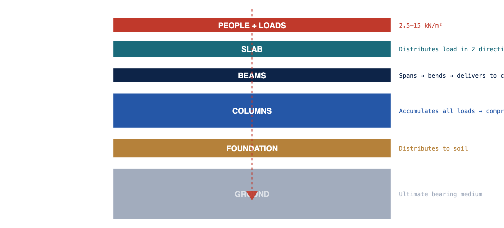
Step-by-Step Load Path in a Reinforced Concrete Building
People, equipment, furniture, finishes. Expressed as kN/m² (kilonewtons per square metre). Typical office floor: 2.5–5 kN/m². Plant rooms: 7.5–15 kN/m².
Distributes load in two directions across its span. The slab is the first structural element the load encounters. It bends under load and delivers reactions to the beams or walls at its edges.
Collect concentrated loads from the slab and span horizontally to the columns. Beams are the primary bending elements. The deeper the beam, the longer the span it can bridge.
Receive the accumulated loads from all beams and slabs above and carry them downward in compression. A ground floor column in a tall building carries the cumulative weight of every floor above it.
Receives the total building load from all columns and distributes it into the ground. Foundation size is determined by soil bearing capacity — softer soils need larger footprints.
The ultimate load-bearing medium. The soil or rock beneath the building must support the entire weight without settling excessively. Ground investigation determines everything.
If a 20-storey building has 5 kN/m² of floor load and a column tributary area of 25 m² per floor, the ground floor column carries: 5 × 25 × 20 floors = 2,500 kN of imposed load, plus self-weight of the concrete structure above. That same column on the 19th floor carries only 5 × 25 × 1 = 125 kN. This is why lower floor columns are always bigger and more heavily reinforced. When a crane installs formwork or lifts precast elements for upper floors, the loads being moved are a fraction of what the completed structure eventually carries at ground level.
Types of Structural Systems
A structural system defines how a building's skeleton is assembled — what materials it uses, how connections are made, and how loads travel. Each system has different implications for which equipment is needed and how the construction sequence unfolds.
Concrete and steel rebar work together — concrete resists compression, rebar resists tension. Columns, beams, and slabs are all cast on site using formwork. The structure gains strength gradually over 28 days of curing. RC is the most common structural system in Africa and the Middle East.
✓ Fire resistant, durable, flexible shapes
✗ Requires formwork on every floor
✗ Slow — must wait for concrete to cure
Steel beams and columns prefabricated off-site and bolted or welded together on site. Floors are typically composite: a steel deck with a thin concrete topping. Steel structures go up faster than RC, but require fireproofing and protection against corrosion.
✓ Precise, predictable performance
✗ Requires fireproofing
✗ Higher material cost than RC
Structural elements (columns, beams, slabs, walls) are manufactured in a controlled factory environment and transported to site for crane installation. Quality is higher and more consistent than cast-in-situ. A precast concrete business requires MATCO equipment: batching plants for production, cranes for installation.
✓ No formwork needed on site
✗ Transport logistics and crane dependency
✗ Less flexible than cast-in-situ
A precast concrete factory is one of the most equipment-intensive construction operations you will encounter. It requires a batching plant to supply consistently graded concrete on demand, a concrete pump to deliver it into steel moulds efficiently, and a crane to demould, stack, and load finished elements. When you visit a precast yard, you are looking at a complete MATCO equipment ecosystem. Understanding the production flow — batch → pump → cure → crane — is the starting point for any sales conversation with a precast producer.
Formwork and Temporary Structures
Before permanent concrete can do its job, temporary structures must do it first. Formwork is the mould that gives concrete its shape while it sets. Shoring is the support system that carries the concrete's weight while it is still liquid and until it reaches design strength. Both are fully structural systems — they carry real construction loads and must be engineered accordingly.
The temporary structure is often more complex than the permanent one. The formwork engineer must design for: the full weight of wet concrete (approximately 24 kN/m³), the dynamic pressure from concrete pump discharge, the impact of workers and equipment on the deck, and the wind loads on exposed vertical formwork faces.
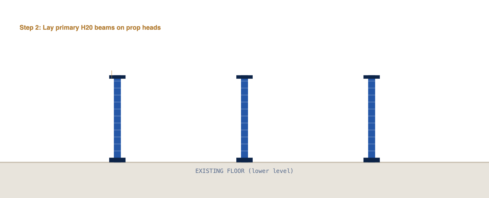
H20 Beam System
The H20 timber beam is the primary spanning element in most flat slab formwork systems. It is an engineered I-section: LVL (Laminated Veneer Lumber) flanges top and bottom provide bending strength, and a plywood web connects them and resists shear. H20 beams are placed in two layers:
Span the longest direction, supported directly by the shoring props. They carry the combined load of the secondary beams and slab above. Typically H20 at 1.2–2.4 m spacing depending on slab thickness and prop layout.
Span the shorter direction, resting on top of the primary beams. They directly support the decking panels. Typically H20 at 0.5–0.75 m centres. The beam spacing controls deck panel deflection and hence final concrete surface flatness.
Shoring Systems
Shoring props are adjustable steel columns that carry the formwork loads down to the floor below (or directly to the ground for the first pour). Each prop has a rated capacity that depends on its extension length — the longer the prop, the lower its capacity due to buckling risk. The prop capacity, spacing, and layout are all calculated to ensure the total slab load is safely transferred.
Concrete does not reach design strength immediately — it gains strength over 28 days. Formwork and shoring must remain in place until the concrete has achieved sufficient strength to carry its own weight and construction loads without the formwork. On a multi-storey building, this typically means the formwork on any floor cannot be struck until the concrete above it has reached at least 75% of design strength, which may take 7–14 days. Stripping formwork too early is one of the most common causes of structural collapse during construction. This waiting period is why large projects have multiple sets of formwork cycling through the building.
Scaffolding
Scaffolding provides access platforms for workers, temporary support for formwork, and protection for workers at height. Tube-and-coupler scaffolding is the most flexible system — standards (vertical tubes) and ledgers (horizontal tubes) are connected by pressed-steel couplers. Frame scaffolding uses pre-fabricated portal frames for faster erection on straightforward facades.
When a client asks whether their scaffolding can carry a concrete pump delivery line, you are being asked a structural question. Pump lines under pressure exert both weight and dynamic surge loads on the scaffold. A standard scaffold platform rated at 2 kN/m² (light duty) cannot safely carry a filled 150mm pump line at high pressure. A structural engineer must verify the scaffold for this load case. Knowing this boundary — and being able to explain why — positions you as a technical resource, not just a quote machine.
Connecting Structural Work to Equipment
Every major structural operation on a construction site has a direct equipment dependency. The ability to map structural activities to equipment needs is the core commercial skill of a construction equipment salesperson.
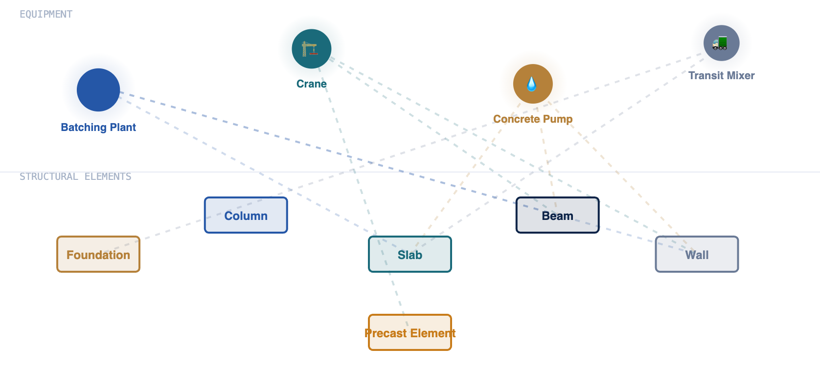
Batching Plant → Concrete Supply for All RC Elements
Every reinforced concrete element requires freshly batched concrete delivered within the workability window — typically 60–90 minutes from batching. Foundations, columns, beams, slabs, walls, and shear cores all require batching plant output. The plant's output rate (m³/hr) must match the pour rate the pump and site crew can handle. A 60 m³/hr batching plant feeding a 50 m³/hr concrete pump creates no bottleneck. A 30 m³/hr plant feeding a 50 m³/hr pump will starve the pump and create construction joint problems in the slab.
A structural contractor asks:
"We have a 400 m³ roof slab to pour in one continuous operation. How do I make sure I
have enough plant capacity?"
The answer involves three calculations:
Pour volume ÷ target pour duration = required batching rate. If the pour
must complete in 8 hours: 400 ÷ 8 = 50 m³/hr minimum. Add 20% contingency for delays: 60
m³/hr target. Your plant must be capable of 60 m³/hr continuous output with zero
interruptions to batch aggregates, cement, or water supply. If reliability is uncertain,
the answer is a second backup plant on standby — or a 90 m³/hr plant in the first place.
Crane → Lifting and Placing Structural Elements
On any RC or steel construction site, the crane is the vertical transportation system for the entire project. It lifts rebar bundles to the floor being cast, positions formwork panels, places precast elements, and moves equipment around the site. Tower cranes are fixed assets that must be positioned to cover the entire building footprint at the required capacity. Mobile cranes are deployed for specific heavy lifts and can be repositioned.
A precast contractor says:
"Our heaviest precast beam is 8 tonnes and it has to be placed 22 metres from the crane
centre."
The calculation is moment: 8 tonnes × 22 m = 176 tonne-metres. The crane's load chart must
show a capacity of at least 8 tonnes at 22 m radius in its current configuration. If it
shows only 6.5 tonnes at that radius, you either need a larger crane, a different
configuration, or you need to position the crane closer to the placement point. Never
quote a crane by its maximum lift capacity — always confirm the capacity at the required
radius.
Concrete Pump → Placing Concrete at Height or Distance
On any multi-storey building, concrete cannot be placed directly from the truck mixer — it must be pumped. The pump receives concrete from the batching plant (via transit mixer), pressurises it, and delivers it through a steel pipeline to the point of pour. Pump selection depends on: vertical height (static head), horizontal distance, pipeline bends (each 90° bend ≈ 30 m equivalent horizontal distance), and concrete slump/mix design.
Concrete pump discharge creates both hydrostatic pressure (the weight of concrete in the pipe) and dynamic surge pressure (pump piston action). The pipeline and its supports must be rated for the maximum working pressure. On a 50-storey building, the hydrostatic head alone from the vertical column of concrete can reach 12–15 bar before pump pressure is added. Pipe clamps, support brackets, and the scaffold or structural element they anchor to must all be verified for this combined load. A pump line that becomes unanchored under pressure is a serious site safety event.
Common Structural Failures
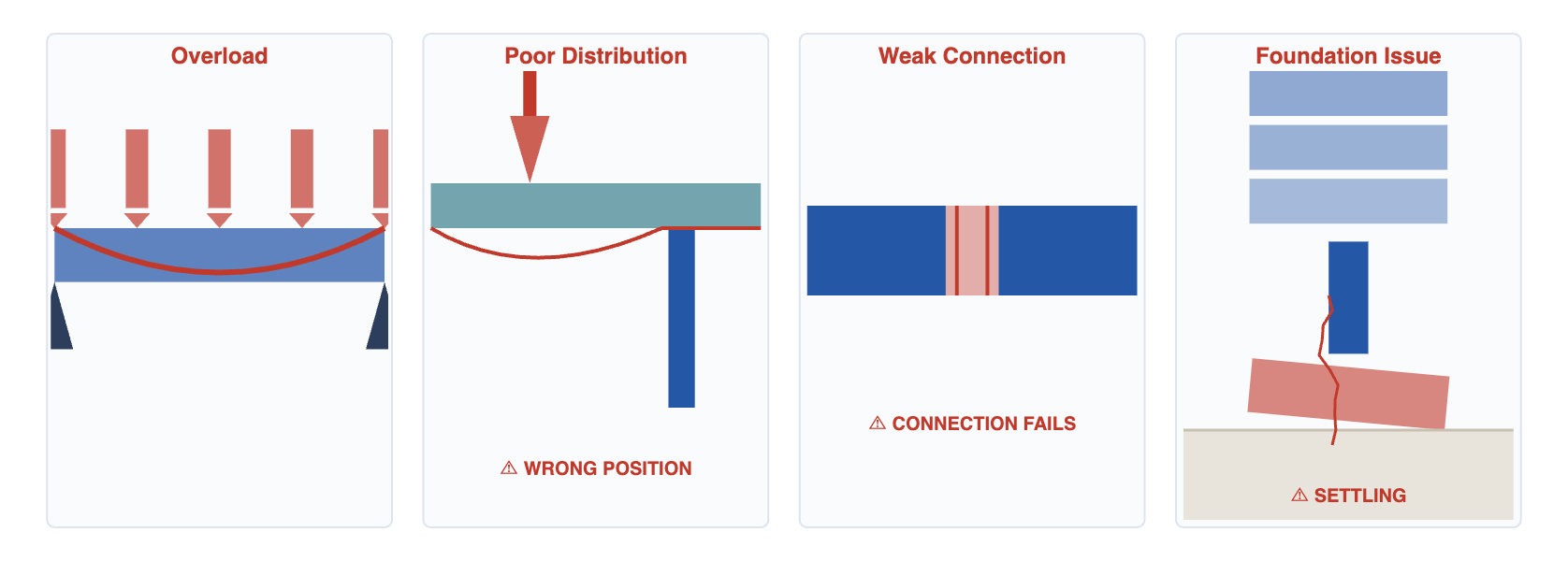
Structural failures in construction are almost always preventable. They result from a small set of recurring causes, most of which are visible in advance to anyone paying attention. Understanding these failure modes helps you recognize risk during site visits and explains why specifications, procedures, and rated capacities exist.
A structural element is subjected to more load than it was designed to carry. This can result from construction activities (storing materials on a slab), design changes (thicker slab than specified), or equipment misuse (lifting beyond crane capacity).
Overloading does not always cause immediate collapse. It may cause cracking, yielding, or permanent deformation that compromises long-term performance without visible failure at the time.
Loads concentrate at unintended points rather than being evenly distributed through the design load path. Concentrated loads cause local overstress even when the total load is within limits. A common case: a point load from a crane outrigger pad lands on a spanning slab rather than on a column or wall below.
Formwork prop positions that do not align with the structural grid below can transfer slab loads to mid-span positions of the supporting floor — exactly where capacity is lowest.
Structures most often fail at connections rather than in the middle of spans. Bolted connections that are under-torqued, welds that are undersized, rebar laps that are too short, and formwork couplers that are loose all represent connection failures. The connection is the point where two load paths join — any weakness there interrupts the entire path.
In precast construction, connection design between elements is the most critical engineering challenge. Unlike cast-in-situ concrete where the structure is monolithic, precast elements are only as strong as their connections allow.
A structurally perfect building above grade can still fail if its foundations yield. Differential settlement — where different parts of the building settle at different rates — causes cracking and distortion of the structural frame. In extreme cases, a foundation that suddenly collapses (due to soil liquefaction, groundwater change, or adjacent excavation) can bring the entire structure down.
Groundwater changes are a major risk in the Middle East and Africa, where seasonal water table variations can dramatically alter soil bearing capacity — affecting crane outrigger stability as well as permanent foundations.
Lesson 5 — Structural Elements Summary Table
| Element | Orientation | Primary Force Type | Key Function | Equipment Connection |
|---|---|---|---|---|
| Beam | Horizontal | Bending (C top + T bottom) | Spans between supports, collects slab loads, delivers to columns | H20 formwork beams, crane spreader beams, steel joist supply |
| Column | Vertical | Compression (+ bending) | Transmits loads from all floors above downward to foundation | Shoring props, precast column crane installation, column formwork |
| Slab | Horizontal plate | Two-way bending + shear | Carries floor loads, spans between beams or walls | H20 beam + prop formwork system, batching plant, pump |
| Foundation | Below grade | Bearing pressure (compression into soil) | Transfers entire building load to ground safely | Batching plant, pump, crane for pile installation |
| Load-bearing wall | Vertical plate | Compression + shear | Carries floor/roof loads AND resists horizontal wind/seismic forces | Formwork panels, scaffolding for access and support |
| Non-LB wall | Vertical | Self-weight only | Partitions space, carries nothing above itself | Crane for precast cladding panels, scaffolding for facade access |
| H20 Beam | Horizontal (temp) | Bending | Temporary formwork element spanning between shoring props | Direct MATCO product — primary + secondary bearer layers |
| Shoring Prop | Vertical (temp) | Compression | Carries formwork + wet concrete load until concrete self-supports | Direct MATCO product — rated by height and capacity class |
Load Path Quick Reference
| Stage | Element | What Happens | Typical Scale |
|---|---|---|---|
| 1 | Imposed Load | People, equipment, finishes act on the floor | 2.5–15 kN/m² |
| 2 | Slab | Distributes load in 2 directions → delivers to beams or walls | 100–300 mm thick |
| 3 | Beams | Span between columns, collect slab reactions, bend under load | 400–1200 mm deep |
| 4 | Columns | Accumulate loads from all floors above → pure compression | 300–800 mm section |
| 5 | Foundation | Spread load across soil area → reduce stress to below bearing capacity | 1.5–5 m wide |
| 6 | Ground | Accepts bearing pressure without excessive settlement | 100–500 kPa capacity |
- Every load must have a complete path to the ground. Interrupting any element in the chain — by removal, overload, or failure — causes the structure above to lose its support.
- Slabs are the primary concrete work on most projects. That means the batching plant, pump, formwork, and H20 beam system are all deployed simultaneously for every slab pour. Understanding slab construction is understanding where your equipment operates.
- Temporary structures carry real structural loads. Formwork and shoring carry the full weight of wet concrete — which can exceed the design load of the finished floor in some configurations. They must be engineered, not improvised.
- Precast construction creates a complete MATCO equipment ecosystem. Batching plant at the factory, pump for mould filling, crane for installation. When you visit a precast producer, you are visiting a potential multi-equipment client.
- Crane capacity is always radius-dependent. A crane rated at 50 tonnes maximum may only lift 14 tonnes at the radius the job requires. Always verify the load chart for the specific lift configuration.
- Column loads accumulate floor by floor. A ground floor column in a tall building carries vastly more load than an upper floor column. Column size, rebar content, and concrete grade all increase toward the base — this governs the concrete specification your batching plant must produce.
- Most structural failures are preventable. Overloading, poor load distribution, weak connections, and foundation issues are all visible or calculable in advance. Your ability to raise these risk points in client conversations adds genuine technical value.